Set up ADAM-6060
This page describes how to set up the ADAM-6060 device to create a basic signaling system.
This page serves as a reference guide for a basic ADAM-6060 setup.
Refer to the official Advantech ADAM-6000 series User manual for in-depth information about the product.
Basic ADAM-6060 setup
Prerequisites
RJ-45 Ethernet cable
Wires of #14-28 AWG (stripped length: 6.5mm) to connect to other hardware
Installed Advantech ADAM/PAX utility software
Physical setup
To set up the ADAM-6060, follow these steps:
Connect the module to the local network via an Ethernet cable.
Connect the module to a power source using the two connectors highlighted
in the image below: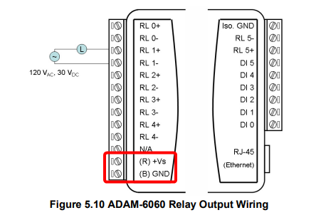
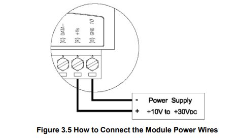
Although ADAM-6000/TCP systems are designed for a standard industrial unregulated 24 VDC power supply, they accept any power unit that supplies input power within the range of +10 to 30 VDC. Power supply ripple must be limited to 200 mV peak-to-peak, and the immediate ripple voltage should be maintained between +10 and 30 VDC. Screw terminals +Vs and GND are for wiring the power supply.
Connect the module to an external device (e.g., an access control turnstile) using the RL1+ and RL1- connectors.
The RL1+ and RL1- connectors in the ADAM/PAX and FORXAI software are labeled DO-1.
ADAM software setup
Configure the ADAM-6060 Module connections using the ADAM utility software.
This setup sends a one-second positive signal from the ADAM-6060 to an external device upon receiving an input (e.g., when a user passes the PPE check).
For a different type of output signal to your external device, please refer to the ADAM-6000 User Manual.
Follow these steps:
Open the Advantech Adam/Apax Utility software on your computer.
You must be connected to the same network as the ADAM-6060.
In the left column, right-click on Ethernet and select Refresh Subnodes.
Right-click on Ethernet again and select Search Device.
(Optional) If you encounter a “No module was found!” error message, follow these steps:Right-click Favorite Group.
Select Add New Group.
Enter a group title and click Add.
Right-click the newly added group.
Select Add New Device.
Select the Ethernet Device tab.
Select the Module Type of your device (generally ADAM-6060).
Enter the IP address of the device. The Systems Administrator will know the IP address of the device.
Enter the password (default password: 00000000).
Click Add.
Select your newly added device in the left-side panel.
Double-click the 6060 device to expand the list of connections.
Select the I/O connection you connected (e.g., DO-1).
Set DO mode to “Pulse output”, then click Apply mode to save.
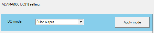
The Pulse output setting generates a pulse through the selected digital output channel. Once the pulse ends, the Digital Output is set back to zero.
(If required) Adjust any other settings based on customer requirements.
Select 6060 GCL.
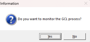
(Optional) Select whether you want to monitor the GCL process. This will display dynamic progress in the schema if the device receives an input signal.
Select PROG at the top of the window.
Program any rules by configuring the Input, Logic, Execution, and Output.
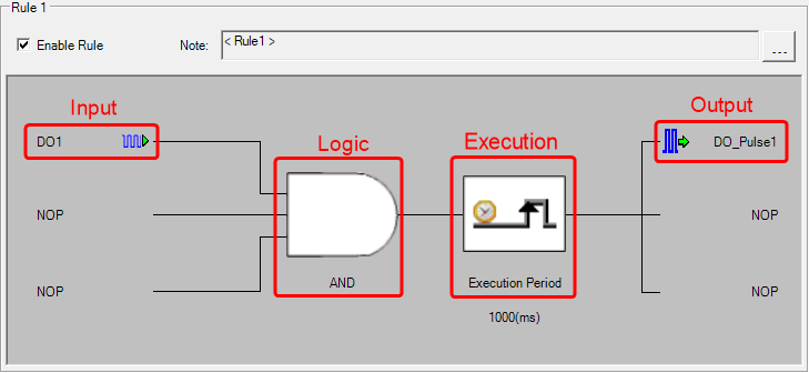
For detailed information on how to configure rules, consult Chapter 8.2 in the ADAM-6000 User manual.
Click the Enable Rule checkbox to enable it.
To save your changes to the device, click the Download project button.
The Download action refers to saving changes to the ADAM-6060 device rather than your computer.
Click RUN at the top of the window.